
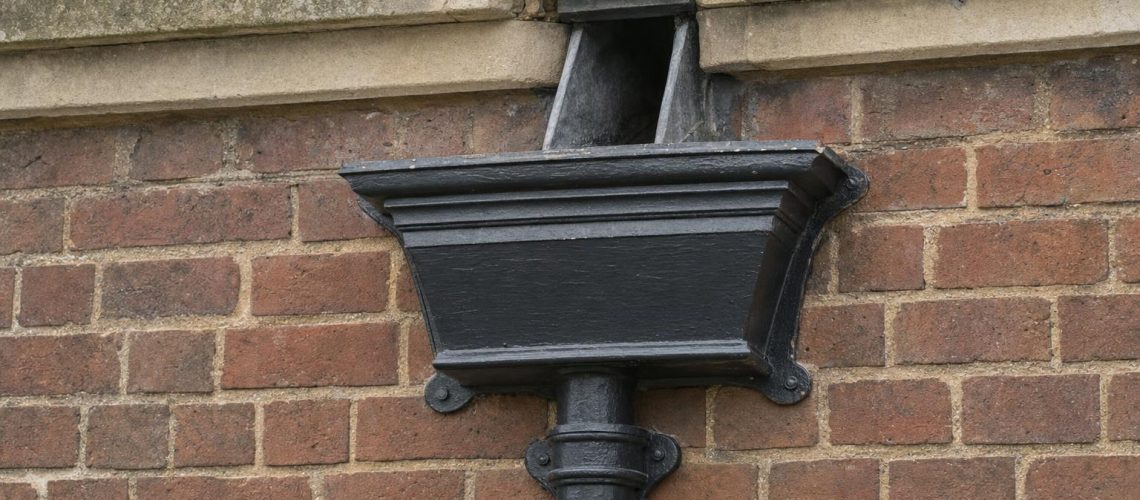
A technical guide for architects, surveyors and conservation officers on sizing cast iron hopper heads against roof area, outlet diameter and downpipe capacity. We explain why the outlet, not the hopper’s volume, governs performance, how parapet chutes and valley gutters change the calculation, and how to specify rainwater heads that cope with today’s heavier downpours on listed and historic buildings.
In summary
Hopper head capacity is determined less by how much water the head can hold than by how much it can discharge. A hopper is a collecting box: water rises inside it until the depth above the outlet (the “head”) pushes the incoming flow down the pipe. The size of that outlet, whether it is fitted with a grating, and the height available inside the hopper above the outlet together decide how much roof area a rainwater head can serve. For eaves gutters on small roofs, Approved Document H gives simple tables. For hoppers fed by parapet, valley or box gutters, BS EN 12056-3 requires higher design rainfall, deeper heads and larger outlets, because an overflow can put water straight into the building. Correctly sized, a traditional cast iron hopper and downpipe will comfortably outperform most roofs they serve; undersized, it becomes the first point of failure.
On this page
A hopper head’s capacity is the flow it can pass to the downpipe without overtopping, and that is set by the outlet diameter and the depth of water the hopper allows above it, not by the hopper’s internal volume. That single principle explains most of the hopper failures we see on period buildings: staining beneath the head, saturated masonry, rotten joists behind a parapet and, increasingly, overflowing in short, intense summer storms.
Rainwater heads, also called hopper heads or simply hoppers, sit where gutters, parapet outlets and valley chutes hand their water over to the vertical cast iron downpipes. On many listed buildings they are also among the most decorative and significant pieces of the elevation, carrying dates, crests and initials. That makes them doubly important: they must work hydraulically, and they must be right historically.
This guide is written for the professionals who specify, approve and install them. It sets out how roof area becomes a flow rate, how that flow passes through a hopper and its outlet, how the downpipe below copes, and where the common specification errors lie. Throughout, we refer to the two documents most often used in the UK: Approved Document H (Part H3, rainwater drainage) for straightforward eaves systems, and BS EN 12056-3 for the more demanding internal, parapet and valley gutters that hoppers so often serve.
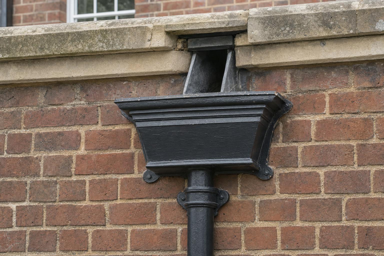
Rainwater heads began as status pieces in cast lead in the sixteenth and seventeenth centuries and became standard cast iron components from the late eighteenth century onwards. Their size and form were set by the roofs they drained and by the casting technology of the day.
After the Dissolution, recycled lead was plentiful, and plumbers turned rainwater heads into display pieces, pierced, tinned and dated, often with the owner’s initials or arms. Downpipes and gutters remained relatively rare until the eighteenth century, when the parapets demanded by urban building legislation hid roofs behind masonry and created the need to bring water down the face of the building in a controlled way. Cadw notes that cast iron superseded lead from the end of the eighteenth century, and by the mid-nineteenth century foundries were producing hopper heads by the thousand from pattern books: flat-backed, tapered, corner and ornamental heads in a range of sizes to suit standard pipe diameters.
The Victorians and Edwardians often copied earlier lead heads, cast dates and initials into iron, and in many cases sized heads generously because they were draining large slate roofs and complex valleys. What they did not have was today’s rainfall data. Many hoppers are entirely adequate; some were marginal from the start and are now being tested by storms they were never designed for. You can see examples of both decorative traditions in our article on armorial and monogrammed hopper heads.
The flow arriving at a hopper is simply the effective roof area multiplied by the design rainfall intensity, expressed in litres per second. Getting both numbers right is the first step in sizing a rainwater head.
Wind-driven rain strikes pitched roofs at an angle, so a steep roof catches more water than its plan area suggests. Approved Document H (Table 1) applies multipliers to the plan area: flat roofs ×1.0, a 30° pitch ×1.29, a 45° pitch ×1.50 and a 60° pitch ×1.87. For pitches over 70°, and for walls that shed water onto a roof or into a gutter, half the elevational area is taken. A tall parapet wall or the face of an adjoining building draining into a valley must therefore be added to the catchment.
For small eaves systems, Approved Document H uses 0.021 litres per second per square metre (75 mm per hour). That figure is adequate where an overflowing gutter simply spills clear of the building. BS EN 12056-3 replaced the older BS 6367 and is more rigorous: it bases rainfall on a two-minute storm and on the consequences of overflow. HR Wallingford’s design manual for the standard notes that the old fixed 75 mm/h figure should no longer be used for UK design, and gives London values of about 0.022 l/s/m² for a one-year storm, 0.056 l/s/m² for a 50-year storm and 0.088 l/s/m² for a 500-year storm.
BS EN 12056-3 assigns four risk categories. Category 1 (a one-year return period) suits eaves gutters that can overflow safely. Categories 2 and 3 apply to valley, parapet and boundary-wall gutters, with return periods of roughly 1.5 and 4.5 times the intended life of the building. Category 4 uses the maximum probable rainfall, for buildings where any water ingress is unacceptable. For a Grade I house or a museum with a parapet gutter over a principal room, the logic of the standard pushes the design rainfall to three or four times the Approved Document H figure.
| Roof situation | Typical design basis | Indicative intensity (l/s/m²) | Flow from 100 m² effective area |
|---|---|---|---|
| Eaves gutter, small roof, safe overflow | Approved Document H | 0.021 | 2.1 l/s |
| Eaves gutter, BS EN 12056-3 Category 1 (south-east England) | 1-year storm | 0.022 | 2.2 l/s |
| Parapet or valley gutter, Category 2–3 (London) | 50-year to 500-year storm | 0.056–0.088 | 5.6–8.8 l/s |
| Exceptional protection, Category 4 | Maximum probable rainfall | From national annex maps | Calculate per site |
The values above are illustrative. Regional figures come from the maps in the UK National Annex to BS EN 12056-3, and rainfall in the north and west differs markedly from London.
The Met Office’s UKCP18 headline findings project that, under a high emissions scenario, the hourly intensity of a typical once-in-two-years summer storm could rise by around a quarter by 2070. Historic England’s guidance on resilient rainwater systems recognises that some historic systems are now failing through inadequate capacity rather than poor maintenance alone. When we size a new or replacement hopper for a building expected to stand for another century, we build in that margin.
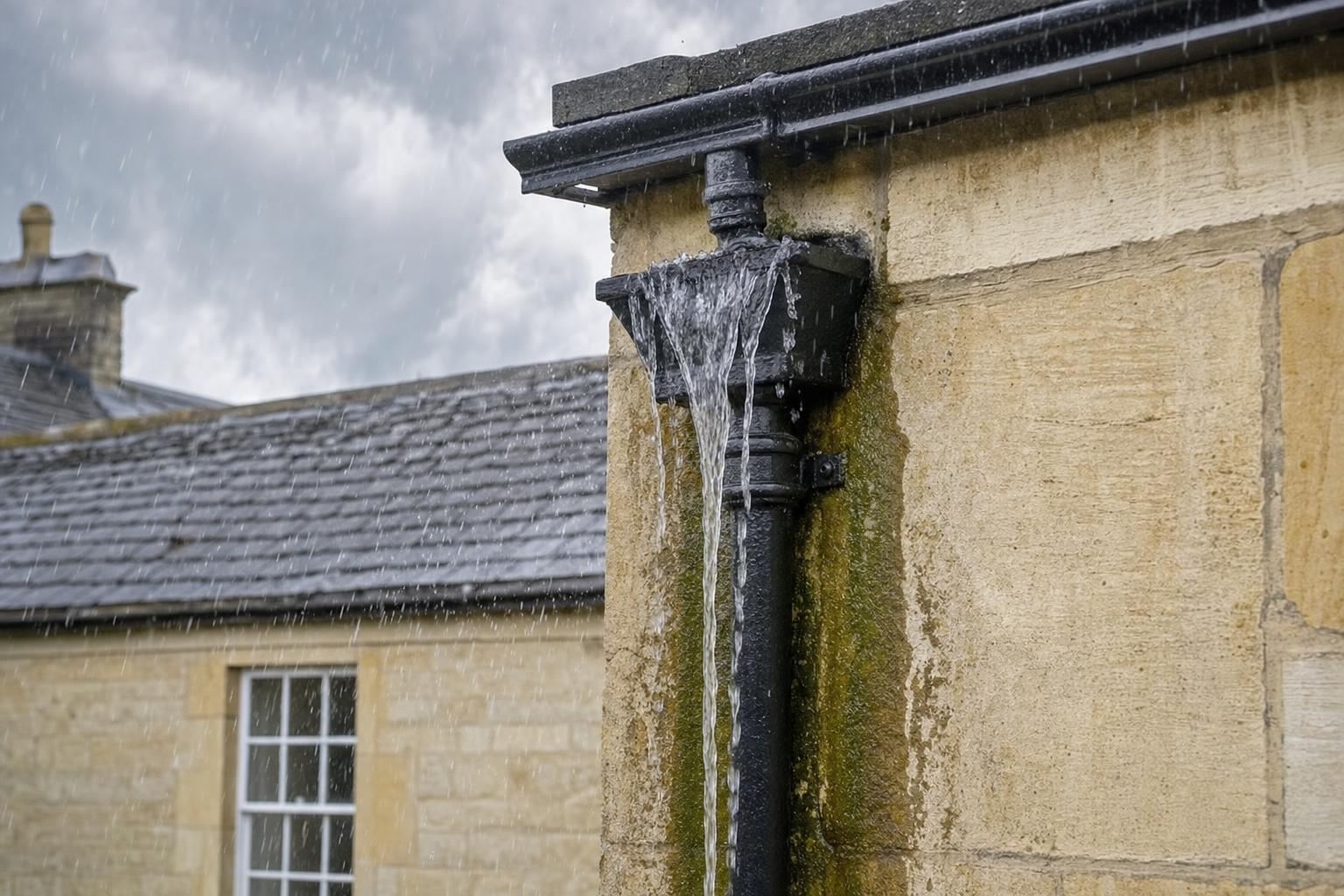
A hopper head works as a collecting box over an outlet: incoming water accumulates until its depth above the outlet is enough to drive the flow down the pipe. Its useful capacity is the outlet discharge at the maximum depth the hopper allows before it overtops, less a safety margin.
It is tempting to think of a larger hopper as a bigger bucket. In practice, a typical ornamental cast iron head holds only some 10 to 20 litres. If 8 litres per second arrive and only 6 can leave, even a generous head fills and overflows within seconds. Volume buys almost no time. What a larger, deeper hopper does provide is a greater depth of water above the outlet, and depth is what increases discharge.
BS EN 12056-3 describes two regimes for a circular outlet. When the water depth (h) is shallow, up to half the outlet diameter (D), water spills over the outlet’s edge like a weir, and capacity rises with h to the power 1.5. Once the depth exceeds half the diameter, the outlet behaves like an orifice and capacity rises only with the square root of the depth. In the standard’s notation, with D and h in millimetres and Q in litres per second:
Two practical conclusions follow. First, outlet diameter is powerful: in the orifice regime, capacity rises with the square of the diameter. Second, once a hopper is working as an orifice, adding depth gives diminishing returns, because doubling the depth increases flow by only about 40 per cent.
Consider a parapet roof of 60 m² draining through a single outlet chute into a hopper. At a Category 2 rainfall of 0.056 l/s/m², the hopper must pass about 3.4 l/s.
| Hopper outlet | Grating fitted? | Depth of water needed above outlet | Minimum hopper depth (adding 25 mm freeboard) |
|---|---|---|---|
| 75 mm (3 in) | No | about 80 mm | about 105 mm |
| 75 mm (3 in) | Yes | about 320 mm | about 345 mm (rarely achievable) |
| 100 mm (4 in) | No | about 40 mm | about 65 mm |
| 100 mm (4 in) | Yes | about 100 mm | about 125 mm |
The table shows why a leaf guard pushed into a hopper outlet so often causes overflowing: it halves the outlet coefficient and can quadruple the depth of water needed. It also shows why stepping up from a 75 mm to a 100 mm outlet and pipe is frequently the most effective single improvement, where the elevation and the conservation officer allow it.
Where a hopper sits directly below a parapet chute, HR Wallingford’s manual treats it as a box receiver. The chute opening acts as a rectangular weir, and its required width (Lw, in millimetres) is approximately 24,000 × Q ÷ h^1.5. For the 3.4 l/s example, with 50 mm of water at the chute, the opening needs to be roughly 230 mm wide and at least 75 mm high. Many historic chutes are narrower, which is why water often builds up in the gutter behind the parapet before the hopper below is anywhere near full. The hopper’s front width must also be enough to catch the jet from the chute at full flow without water overshooting it.
A vertical cast iron downpipe of the same nominal bore as the hopper outlet will usually carry more water than the outlet can deliver, so the pipe is rarely the limiting factor. It must, however, never be smaller than the outlet, and its offsets and connection to the drain matter.
BS EN 12056-3 sizes rainwater pipes using the Wyly-Eaton relationship, assuming the pipe runs about one-third full with a ring of water around an air core. On that basis, indicative capacities are roughly 3.4 l/s for a 65 mm pipe, 5 l/s for 75 mm, 10.7 l/s for 100 mm and 31 l/s for 150 mm. Comparing those figures with the outlet flows above shows how much spare capacity a vertical pipe has.
The weak points lie elsewhere. Offsets flatter than about 10° behave like gutters, not vertical pipes, and should be sized accordingly; that is one reason the traditional steep swan-neck offset works so well. Shoes discharging onto lower roofs concentrate flow, and Approved Document H calls for a distributor pipe where a large area discharges onto a lower roof. Below ground, a historic drain may have less capacity than the pipe above it. Our guide to cast iron downpipe sizes covers pipe selection in more detail, and our article on blocked downpipes explains how quickly a partly blocked pipe defeats any calculation.
Size the hopper from the catchment it serves: total the effective areas of every gutter, chute and wall draining into it, apply the right design rainfall, then choose an outlet and hopper depth that pass that flow with freeboard to spare. The checklist below is the sequence we follow on survey.
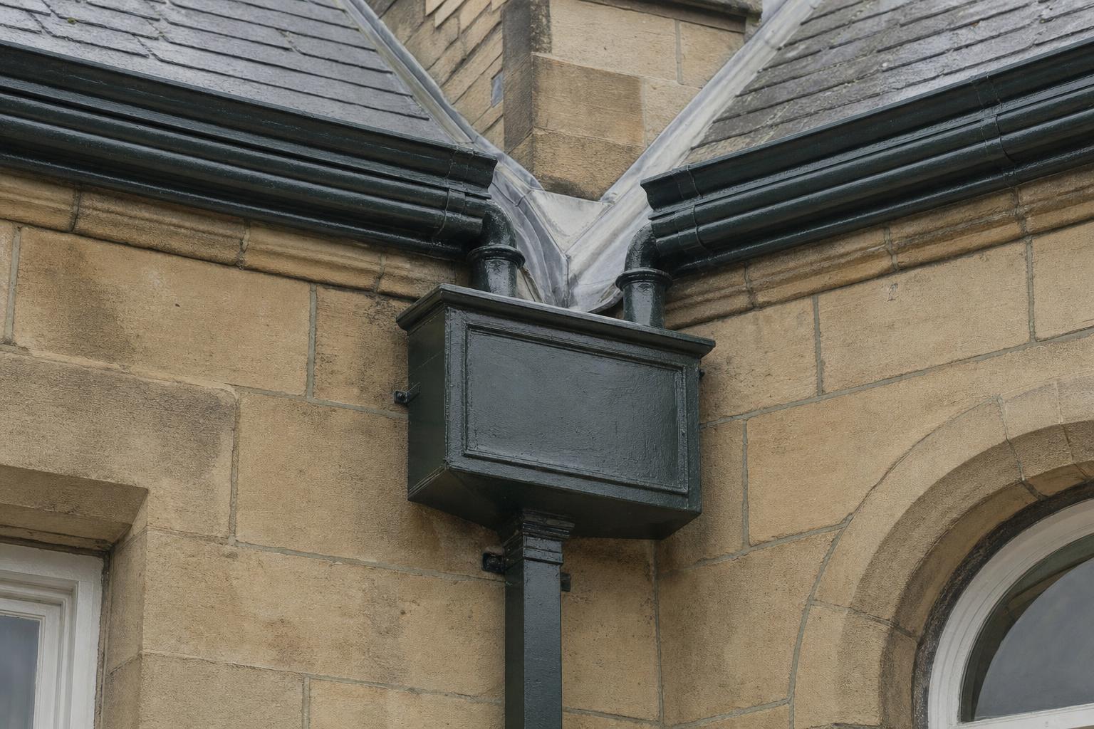
Roof geometry matters as much as area. A long eaves run with a single outlet at one end must carry all its water to that end; moving the outlet to the centre, or adding a second hopper and pipe, roughly halves the flow each must handle. Corner hoppers, such as our Regent corner hopper, are ideal where two gutter runs meet, but they then receive the combined flow of both.
| Our hopper type | Typical use | Sizing note |
|---|---|---|
| Pultney tapered hopper | Single eaves outlet on domestic elevations | Shallow form; best with modest flows and no grating |
| Rectangular box hopper No.46 | Parapet chutes, valley outlets, two inlets | Deep, wide body suits box-receiver duty |
| Regent hopper No.1 | Ornamental Georgian and Victorian elevations | Check depth above outlet against design flow |
| Trenton hopper No.12 (355 × 230 × 305 mm) | Larger catchments, institutional buildings | Generous depth gives useful head |
| Bespoke and copy cast heads | Matching a surviving original | Can be cast with a larger outlet spigot where justified |
Our full range of cast iron hopper heads covers round, square and rectangular outlets to suit the corresponding pipe systems.
On a listed building, any change to the size, position or pattern of a rainwater head is likely to need Listed Building Consent, so capacity improvements should be justified and as discreet as possible. Historic England’s guidance on upgrades or alterations to rainwater goods accepts that changes made to cope with increased rainfall are likely to be acceptable where they are kept to what is necessary, and that new sections should match the original profile and material.
In order of preference, the options are usually:
Where a historic head is decorative, dated or armorial, we recommend repair and retention first. If replacement is unavoidable, our bespoke and copy casting service reproduces the original pattern exactly, and can incorporate a larger outlet without altering the visible face. Our frequently asked questions cover ordering, finishes and delivery in more detail.
The most common hopper errors are sizing from the old 75 mm per hour figure on parapet roofs, fitting gratings into outlets, and ignoring the second catchment that arrives through a chute or valley. Each of these is avoidable at specification stage.
Standard stock hopper heads and pipes are available for prompt despatch, while bespoke and copy cast heads typically take 8 to 10 weeks from pattern confirmation. Building that lead time into the programme, and confirming the hydraulic design before the pattern is made, avoids delay and expensive rework.
Where a building has complex parapets, valleys, multiple catchments or a history of water ingress, we recommend our chargeable site survey and visit before specification is finalised. We measure the catchments, record outlet and chute sizes, assess the condition of historic heads and confirm whether a larger outlet or an additional pipe is justified. For copy casting, clients typically provide photographs, a measured drawing or a surviving fragment, and we confirm quantities and the casting route from there.
All of our hopper heads can be supplied primed or finished in our in-house linseed oil paint system, a vapour-permeable, heritage-appropriate finish that is easy to maintain without stripping back to bare metal.
These are published examples drawn from list entries and project records. None is a Tuscan Foundry project.
Levens Hall, Cumbria (Grade I)
Levens Hall, largely remodelled in the late seventeenth century for Colonel James Graham, has one of the best documented sets of lead rainwater heads in England. Its list entry records heads inscribed “IGD 1692” and “1691”, others marked “I & DG 1700” in the courtyard, and gilded heads with crowns and the initials “MA” dated 1787 and 1788 on the service wing. They show how heads recorded each phase of building, and why any capacity improvement there should leave the historic heads in place.
St Mary’s Church, Leighton Bromswold, Cambridgeshire (Grade I)
Restored by the poet George Herbert from 1626, St Mary’s retains an elaborately shaped rainwater head with an enriched cornice dated 1632, and the Royal Commission inventory records a pair of north transept heads dated 1634 with embattled tops and painted decoration. Church heads like these serve long, low roofs and are often small for their catchment, so on ecclesiastical buildings we look first at chutes, falls and maintenance before suggesting any change to an outlet.
Knole, Sevenoaks, Kent (Grade I)
Knole’s Jacobean lead rainwater heads, made for Thomas Sackville, were singled out by W. R. Lethaby in his 1893 study Leadwork for their bright tinned patterns and piercing. Heads of this quality are significant artefacts in their own right. Where a modern catchment calculation shows such a head is undersized, the conservation answer is normally to relieve it, with an additional discreet pipe or improved feed, rather than to alter or enlarge the historic head itself.
Victoria and Albert Museum, London (Grade I)
The V&A holds cast iron rainwater heads made by Thomas Elsley & Co in 1905 for Aston Webb’s great front range, marked “VAM 1905” on the face and with the maker’s name cast on the back. They are a reminder that institutional buildings of the period used substantial cast iron heads designed to serve large roofs behind parapets, and that a museum is precisely the kind of building for which BS EN 12056-3 calls for the highest rainfall category.
Drummuir Castle, Moray (Category A)
Built in 1846–47 to designs by Thomas MacKenzie, with additions in 1865, Drummuir Castle’s Historic Environment Scotland listing records rainwater goods dated 1847 and 1865, matching its two building campaigns. Dated heads like these help surveyors read a building’s history, and they demonstrate the value of copy casting: a replacement can carry the original date and pattern, cast in iron, with an outlet sized for today’s rainfall.
Calculate the effective area of every roof slope and wall draining into the hopper, multiply by the design rainfall intensity to find the flow in litres per second, then choose an outlet diameter and hopper depth that pass that flow with at least 25 mm freeboard. Eaves systems can use Approved Document H; parapet and valley gutters should be designed to BS EN 12056-3.
Only slightly. A cast iron hopper holds perhaps 10 to 20 litres, which fills in seconds in a heavy storm. What prevents overflowing is the outlet diameter and the depth of water the hopper allows above the outlet, so a deeper head with a larger outlet performs far better than a wider, shallow one.
We advise against it. BS EN 12056-3 halves the capacity of an outlet fitted with a grating, which can quadruple the depth of water needed to pass the same flow. Protect the gutter or parapet outlet upstream instead, and clear the hopper during routine maintenance.
The downpipe should be at least the same size as the outlet, so a 100 mm (4 inch) outlet takes a 100 mm pipe. A vertical 100 mm cast iron pipe can carry around 10 litres per second, comfortably more than the outlet usually delivers, provided offsets are steep and the drain below is clear.
In most cases, yes. Changing the size, pattern or position of a rainwater head on a listed building affects its character, so consult the conservation officer first. Historic England accepts that proportionate changes to cope with heavier rainfall can be appropriate, especially where the original pattern is retained or copy cast.
The usual causes are an outlet that is too small for the catchment, a grating or debris in the outlet, a parapet chute delivering a jet that overshoots the hopper, or a second roof discharging into it that was never allowed for. A site survey will identify which applies before any parts are ordered.
Bespoke and copy cast hopper heads typically take 8 to 10 weeks from pattern confirmation, while standard stock heads are available for prompt despatch. We work from photographs, measured drawings or a surviving original, and recommend a site visit where the head is ornate, damaged or serving a complex roof.
Hopper head capacity comes down to a simple chain: catchment area, design rainfall, outlet size and the depth of water the hopper can hold above that outlet. Get the chain right and a traditional cast iron rainwater head will serve a building for generations; get one link wrong and it becomes the weakest point in the roof drainage. For parapet, valley and box gutters, design to BS EN 12056-3 rather than eaves-gutter rules, keep gratings out of outlets, provide a visible overflow, and allow for the heavier storms now forecast.
At Tuscan Foundry Products we have supplied cast iron rainwater goods since 1893, and hopper heads remain one of the components we are asked about most. We hold standard hopper heads, round, square and rectangular downpipes and fittings for prompt despatch, copy cast historic heads to their original pattern, typically within 8 to 10 weeks, and finish them in linseed oil paint in our own workshop. When a building’s rainwater heads need to be checked against today’s rainfall, our chargeable site surveys give architects and conservation officers the measurements and calculations they need to specify with confidence. Call us on 0333 987 4452 or contact us to discuss your project.