
Installing Conservation Rooflights in Traditional Roofs: Detailing, Flashings and Weathering
Forming an opening in a historic roof is the part of a rooflight project that cannot be undone. This is how the work is sequenced, how the unit is weathered into slate, plain tile and pantile, and what happens to the water once the slope has been interrupted.
In summary
Installing a conservation rooflight in a traditional roof is a sequence of seven stages: survey and set out, strip back and record, trim the structural opening, resolve the insulation and vapour control line, fit and level the unit, weather it into the covering with soakers and flashings dressed under the head and over the cill, and reinstate the covering to BS 5534. The details that most often fail are the head flashing, where water concentrated by the rooflight is delivered behind rather than onto the covering; the underlay, which must be dressed and supported rather than cut and left; and the cold bridge at the frame perimeter, which produces condensation on the reveal. A rooflight also changes how water reaches the gutter, and the rainwater calculation should be revisited.
On this page
Introduction
Everything else in a rooflight project is reversible in principle. The consent can be varied, the unit can be changed, the blind can be added later. Cutting the opening cannot be undone, and on a historic roof it removes fabric that is often the least altered part of the building.
That is why installation deserves the same attention as specification. A well-chosen conservation rooflight badly weathered is a worse outcome than a modest unit installed properly, because the failure mode is water in the roof structure rather than a visual compromise.
This article covers the practical work: sequencing, the structural opening, the junction with insulation and vapour control, how the unit is weathered into the three common traditional coverings, condensation, and what an interrupted roof slope does to the rainwater system below it. It assumes the consent position is settled and the product chosen; if it is not, our specification guide and our guide to Listed Building Consent cover those stages.
It is written for contractors, clerks of works and the architects and surveyors who have to inspect the result.
The installation sequence
A conservation rooflight installation runs in seven stages, and the order matters because three of them are inspection points that cannot be revisited once the covering is back on.
| Stage | Work | Inspection point |
|---|---|---|
| 1 | Survey, set out and confirm the opening position against the rafter layout | Before any stripping |
| 2 | Strip back the covering, record what is found, expose the structure | Yes — record before alteration |
| 3 | Trim the structural opening: cut rafters, install trimmers and trimming rafters | Yes — before anything is covered |
| 4 | Resolve the insulation line, vapour control layer and underlay at the perimeter | Yes — before the unit goes in |
| 5 | Fit, level and square the unit; check operation before it is weathered in | |
| 6 | Weather in: soakers, side flashings, head flashing, cill | Yes — before reinstatement |
| 7 | Reinstate the covering to BS 5534; make good internal lining and decoration |
Stage 1: survey and set out
Set out from the inside and the outside, and reconcile the two before anything is touched.
From inside, establish the actual rafter centres — on a historic roof these are rarely regular, and hand-cut oak or elm rafters may vary by 50 mm or more across a bay. From outside, establish the batten gauge and the slate or tile module, because a rooflight that falls awkwardly against a course produces a cut-slate detail that is both ugly and vulnerable.
The commonest set-out error is positioning the rooflight from the drawing rather than from the roof. A 20 mm shift up or down the slope to land on a clean course line is almost always worth taking, and almost always available.
Where the roof structure is not fully understood, or access is difficult, a site survey before the scaffold is designed is money well spent. It is a chargeable service, and it is considerably cheaper than discovering a purlin in the wrong place with the covering already off.
Stage 2: strip back and record
Strip generously — at least two courses beyond the anticipated flashing line on each side, and more at the head. Working in a tight opening is how slates get broken and flashings get skimped.
Record what is exposed. On a listed building this may be a condition of consent; on any historic building it is good practice. Old timber roofs were hand-made, frequently in oak or elm, and often carry carved detail and carpenter’s marks. Historic England makes the point that the roof is an important part of why a house is interesting even where it is not seen. Photograph the structure before it is altered, and note any marks on the members being cut.
Salvage the covering. Sound slates and tiles from the opening are the correct material for making good around it, and a reclaimed slate from the same roof will always match better than a bought-in one.
Stage 3: the structural opening
The opening is formed by cutting the rafters crossing it and transferring their load to trimmers at head and cill, supported by trimming rafters at each side. This is standard carpentry, but on a historic roof there are three heritage-specific points.
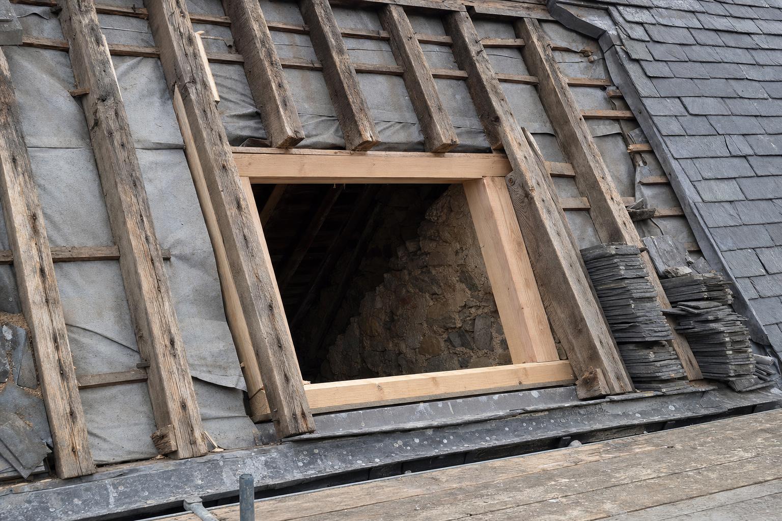
Cut as few members as possible. A rooflight sized to fit between two existing rafters requires no cutting at all, and on a historic roof that is worth designing for even at the cost of a narrower unit. The historic portrait format works in your favour here.
Retain what you cut. Cut rafter ends stay in place, carried by the trimmer. They are historic fabric and they tell the story of the roof.
Match the new timber sensibly. New trimmers should be structurally adequate and visually honest — matched in section and species where they will be seen, and not disguised as original. Reversibility is worth designing in, but Historic England Advice Note 2 is explicit that reversibility alone does not justify alteration, so do not lean on it as an argument.
Where the opening crosses a purlin, stop. That is a structural intervention of a different order and needs an engineer, and on a listed building it is likely to need the consent varying.
Stage 4: insulation, vapour control and underlay
This is the stage that determines whether the rooflight causes problems in five years, and it is the stage most often rushed.
The insulation line must be continuous to the frame. Where insulation stops short of the rooflight frame, the perimeter becomes a cold bridge, the reveal runs cold, and condensation forms on the plaster or the timber lining. This is the most common defect we hear about after installation, and it presents as a damp patch that the occupant attributes to a leak.
The vapour control layer must be continuous and sealed to the frame. Warm moist air finding its way into the roof structure around the frame perimeter will condense on the cold side. Sealing the VCL to the frame with a proprietary tape is a five-minute operation that prevents a recurring problem.
The underlay must be dressed and supported, not cut and abandoned. Underlay should be cut generously, dressed up and over the rooflight upstand and supported so that it cannot sag and pond. BS 5534 limits underlay drape to a maximum of 15 mm in the general case, and around a rooflight the detail is a critical junction for wind uplift. A flapping or sagging underlay at a rooflight head is a route for wind-driven water.
Do not block the ventilation path. On a cold roof, the rooflight interrupts the ventilated void. Check that air can still pass around the opening, or provide an alternative route. We discuss the wider behaviour of moisture in traditional buildings in our article on the problem with condensation, written by a Chartered Surveyor and relevant to every part of this stage.
Stage 5: fitting the unit
Fit, level, square and — critically — operate the unit before it is weathered in. A conservation rooflight that binds because the opening is out of square is a straightforward fix at this stage and an expensive one once the flashings are dressed and the covering reinstated.
Check the unit sits at the intended height relative to the batten gauge. This is what determines whether the finished rooflight is genuinely flush or merely low, and it is the moment at which the specification either becomes real or does not.
On an undulating historic roof plane — common on seventeenth-century plain-tiled roofs and on hand-dressed stone slate — do not adjust the roof to suit the rooflight. Bed the unit to follow the plane. A rooflight sitting proud at one corner because the roof was flattened around it looks far worse than one that follows the roof.
Weathering into traditional coverings
The principle is the same for every covering: water arriving from above must be carried onto the covering below, never behind it, and the side flashings must be interleaved with the covering rather than laid on top of it.
Natural slate
Slate is the most straightforward covering to weather a rooflight into, and the most commonly encountered on the roofs that receive conservation rooflights.
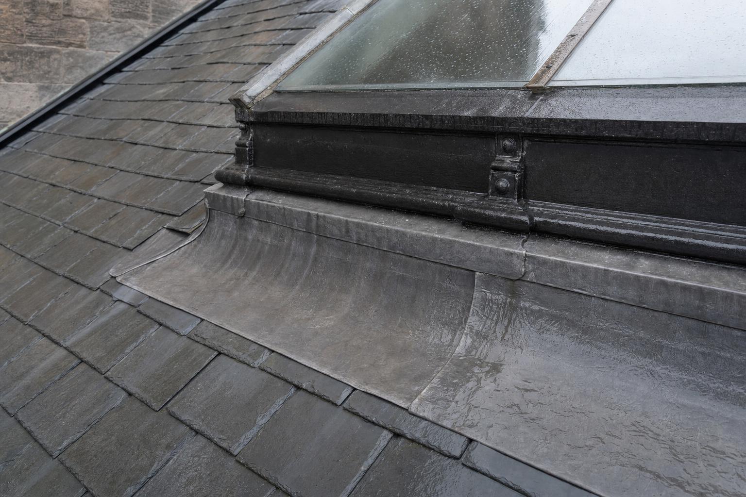
- Sides: lead soakers interleaved with each slate course, one per course, turned up against the rooflight upstand. Soakers are the correct detail; a continuous side flashing laid over the slates is not.
- Head: a lead back gutter or head flashing dressed up the upstand and out over the slates below, with the slates above lapping onto it. The head is where the concentrated flow arrives and it is the detail that fails most often.
- Cill: an apron dressed down over the slates below, with adequate lap.
- Code: lead thickness appropriate to the length of the detail and the exposure, following current leadwork guidance.
Slate’s thin section means the frame profile for a slate roof is slimmer than for a tile roof — some manufacturers supply separate slate and tile profiles for exactly this reason, and specifying the wrong one produces either a proud unit or a covering that cannot be dressed cleanly against it.
Plain tile
Plain tiles are thicker and have a double lap, which changes the geometry.
- The rooflight upstand needs to clear the tile thickness, so the frame profile is deeper.
- Side soakers are still the correct detail, sized for the double lap.
- Tile-and-a-half tiles at the course ends adjacent to the opening avoid narrow cut tiles, which are weak and prone to slipping.
- On hand-made plain tiles with camber, expect the plane to be uneven and bed accordingly.
Pantile and single-lap tiles
Single-lap tiles are the most demanding of the three because the profile is deep and the interlock cannot be interrupted.
- The side detail usually requires a purpose-made soaker or a proprietary skirt that accommodates the profile, dressed into the pan.
- Cut tiles at the opening must be mechanically fixed. BS 5534 removed mortar as a sole means of fixing and requires perimeter tiles to be fixed twice — the tiles around a rooflight opening are perimeter tiles for this purpose.
- On old clay pantiles the profile varies between tiles, and a dressed lead detail is generally more forgiving than a proprietary one.
Stone slate
Stone slates are heavy, thick, variable and diminishing in course up the roof. Weathering a rooflight into them is specialist work.
- Expect to need an oversized frame profile for the covering thickness.
- The diminishing course means the rooflight interrupts a changing module; set out against the courses it actually sits in.
- Historic England publishes a technical advice note on stone slate roofing, and on a listed building a roofer experienced in the local tradition is not optional.
Detailing the water
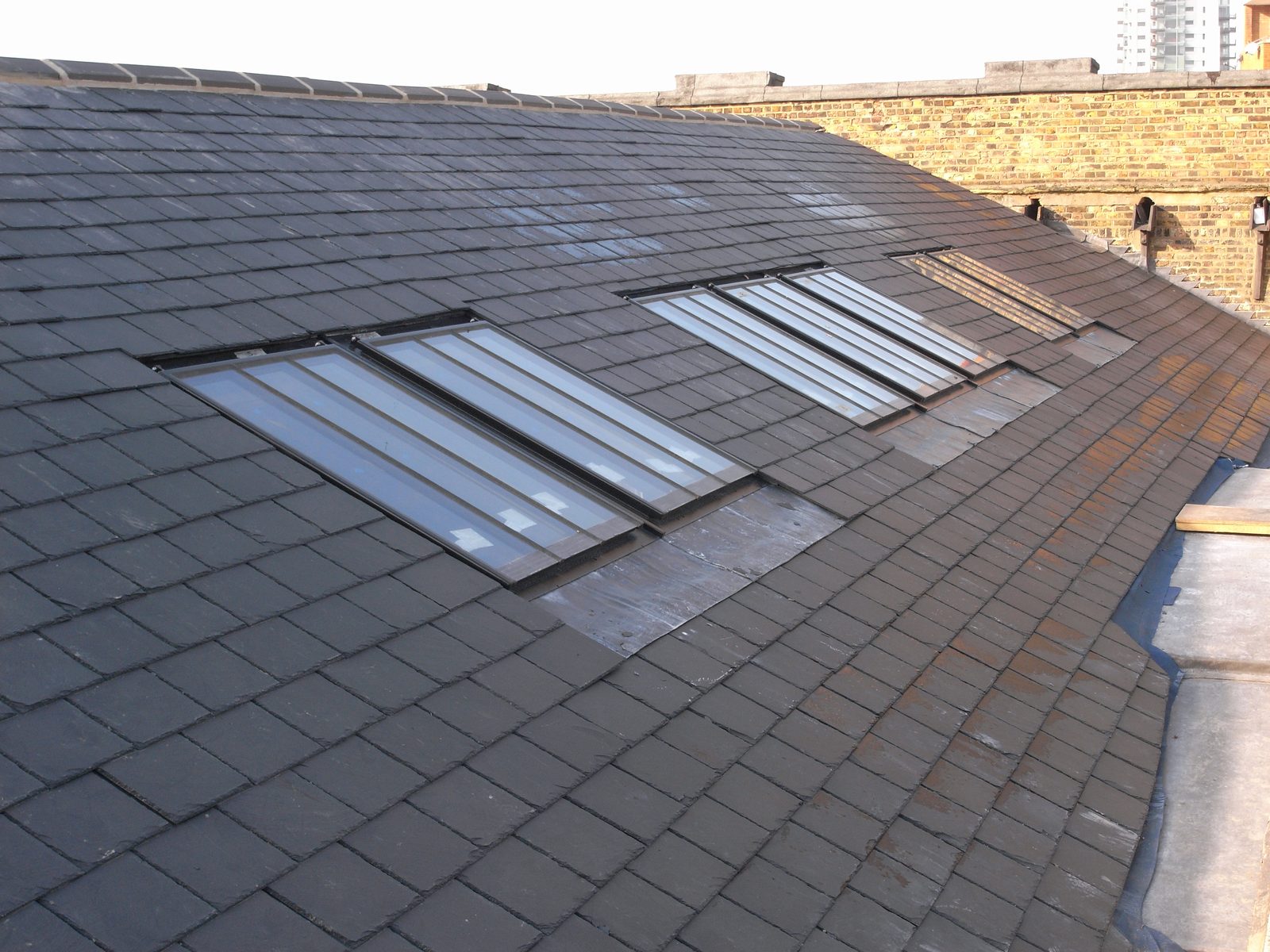
A rooflight interrupts sheet flow down a roof slope and concentrates it. Water that would have run evenly over the covering is diverted around the unit, arriving at the sides in a locally heavier flow and — at the head — concentrating against the upstand before being turned out.
This has three practical consequences.
The head detail carries more water than it looks. Size the back gutter for concentrated flow, not for the notional catchment of a small opening. On a long slope above the rooflight, this is the single most loaded detail in the installation.
The covering below the rooflight sees locally heavier flow at the sides. Fixings and laps in that zone deserve attention, and this is one of the places where BS 5534’s mechanical fixing requirements earn their keep on a historic roof.
The gutter below sees a changed flow pattern. The total volume is unchanged, but its distribution along the gutter is not. On roofs where capacity was already marginal — common on Victorian buildings with original cast iron gutters sized for a different rainfall expectation — this can be the difference between a gutter that copes and one that overtops in heavy rain.
Where a rooflight sits above a valley, a secret gutter or a parapet gutter, look harder. Concentrated flow into a valley is a recognised problem, and a valley that was adequate before may not be after. Where the discharge point is a rainwater head, the head is doing more work than it was.
Our recommendation is straightforward: revisit the rainwater calculation whenever an opening is introduced into a slope. It takes an hour. Re-lining a ceiling because a gutter overtopped takes considerably longer.
If the rainwater goods are being replaced or repaired as part of the same works — which, given that the scaffold is already up, they frequently are — this is the moment to size them correctly. We cover the principles in our guidance on cast iron guttering for heritage buildings, and on churches in particular the care and maintenance of rainwater systems is a subject where the consequences of getting it wrong arrive quickly.
Reinstating the covering
Reinstatement is governed by BS 5534:2014+A2:2018, Slating and tiling for pitched roofs and vertical cladding — Code of practice, and the requirements that bear most directly on a rooflight installation are:
- Mechanical fixing. Mortar is no longer acceptable as the sole means of securing a covering. Perimeter tiles must be fixed twice, and the tiles and slates around a rooflight opening are perimeter units.
- Underlay specification and wind uplift. The underlay must be specified for its uplift resistance, and the detailing at the rooflight upstand is a critical junction.
- Batten grading and specification. Battens cut and refixed around the opening must meet the same specification as the original run.
- Drape limits. Underlay drape is limited, and around a rooflight the underlay must be supported so it cannot sag into the flashing zone.
There is a genuine tension here between BS 5534 and traditional detailing, and it is worth naming rather than glossing over. The standard’s mechanical fixing and uplift requirements were written with modern coverings in mind and can sit awkwardly with historic practice — nail patterns that split thin natural slate, for instance, or fixings that are visually intrusive on a hand-dressed stone slate roof. On a listed building the resolution usually lies in discussion between the roofer, the building control body and the conservation officer, and it is better had before the covering comes off than after.
Use the salvaged material for the courses immediately around the opening, and hold back the best of it for the visible face.
Condensation: the failure that gets blamed on the rooflight
We hear about condensation more often than we hear about leaks, and it is worth being clear about what causes it.
A rooflight introduces a cold surface into a warm space. Glass is colder than the surrounding ceiling in winter, and the frame perimeter is colder still where insulation is discontinuous. Warm moist air reaching that surface condenses. This is a building physics outcome, not a product defect, and it is prevented at installation rather than corrected afterwards.
The preventable causes, in order of how often we encounter them:
1. Insulation not carried fully to the frame, leaving a cold perimeter. The visible result is a damp line around the reveal.
2. Vapour control layer not sealed to the frame, allowing moist air into the structure.
3. Ventilation path blocked by the opening, so the roof void no longer ventilates as designed.
4. Reveal detailed without a splay, trapping still air against the glass. A splayed reveal improves both air movement and daylight.
5. Insufficient purge ventilation, so moisture generated in the room is never removed. If the rooflight is the room’s only opening, its opening angle determines whether Approved Document F is satisfied — below 15 degrees it does not count for purge ventilation at all.
Traditional buildings behave differently from modern ones, with vapour-permeable construction that absorbs moisture and allows it to evaporate. Approved Document L makes the point directly in its guidance on historic and traditional dwellings: energy efficiency should be improved only where doing so will not cause long-term deterioration of the fabric. The same caution applies to a rooflight installation that seals a previously breathing roof void.
Our article on the problem with condensation sets out the underlying behaviour in more detail.
Aftercare and maintenance
Access. A rooflight on a steep slate roof will not be cleaned often, which is why self-cleaning outer coatings are near-universal on conservation units and worth specifying.
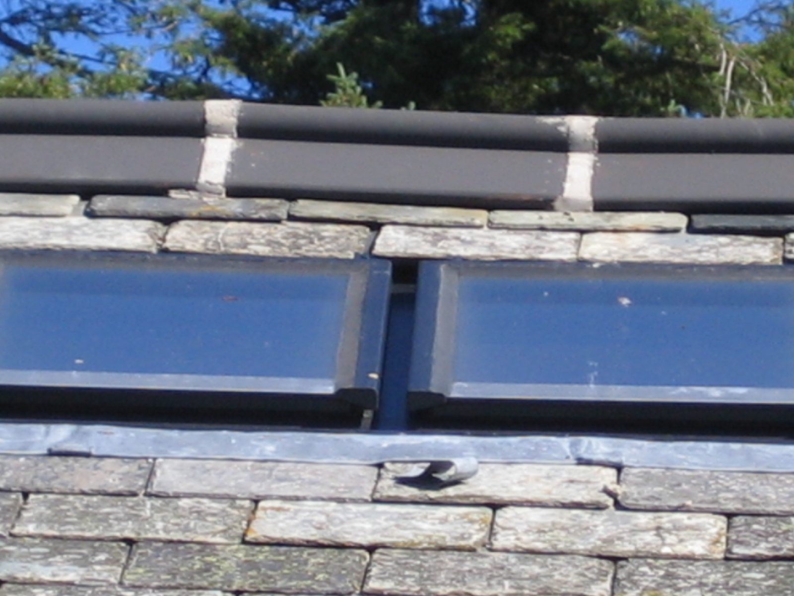
Annual check. Inspect the head flashing and the side soakers at the same time as the gutters. Both are checked from the same ladder or platform, and both fail in the same weather.
Ironmongery. Solid brass and chrome winder mechanisms need occasional lubrication and little else. Electric actuators need the power supply checked.
Frame coating. Powder-coated steel frames need the coating kept intact, particularly at the edges and around fixings, which is where failure starts. Touch in chips promptly. Where a historic cast iron frame has been repaired and repainted, linseed oil paint is the heritage-appropriate system and behaves quite differently from a modern coating — it wears rather than fails, and is maintained by recoating rather than stripping.
Record the installation. Keep the approval drawings, the flashing details and the photographs of the open structure. On a listed building this becomes part of the building’s record, and on any building it is what the next surveyor needs.
Illustrative scenarios
The scenarios below are illustrative composites drawn from typical projects. They are not specific buildings or Tuscan Foundry commissions.
A Tithe Barn, Somerset — Grade II*
A stone-slated cruck-framed barn being converted to a meeting hall. Two rooflights were consented on the rear slope, sized to fit between existing rafters so that no historic timber was cut at all. The diminishing stone slate course meant each unit sat in a different module, and both were set out from the courses rather than from the drawing. The head flashings were sized for concentrated flow from a long slope above; the original detail proposed was a third of the depth finally installed.
A Georgian Rectory, Norfolk — Grade II
A pantiled roof where a previous rooflight installation had been weathered with a continuous side flashing laid over the tiles rather than soakers dressed into the pans. Water had been tracking behind the covering for several years, and the rafter feet below showed decay. The remedial work involved stripping back two metres each side, forming proper soaker details, and replacing three rafter ends — a straightforward job that the original installation should have avoided.
A Victorian Terrace, Powys — Unlisted, Conservation Area
A loft conversion in a Welsh slate terrace. The occupant reported a persistent damp line around the rooflight reveal, attributed to a leak. Investigation found the flashings sound and the insulation stopping 60 mm short of the frame on all four sides. The perimeter was a cold bridge and the “leak” was condensation. Correcting it required opening the reveal, carrying the insulation to the frame and sealing the vapour control layer — none of which would have been necessary had it been done at stage four.
A Parish Church Aisle, Gloucestershire — Grade I
A rooflight consented by full faculty over a new vestry area in a nineteenth-century aisle. The rooflight sat directly above a lead-lined valley gutter that discharged into a cast iron rainwater head. The valley had been marginal before the works; concentrating flow around the rooflight made it overtop in the first autumn storm. The valley was widened and the rainwater head replaced by copy casting from the surviving original — work that should have been identified at the rainwater calculation stage.
A Coaching Inn, North Yorkshire — Grade II, Conservation Area
A plain-tiled roof of markedly uneven plane, hand-made tiles with pronounced camber. The contractor’s initial approach was to level the tile plane locally so the rooflight would sit true. This was stopped and the unit was instead bedded to follow the roof, with the frame packed and the soakers dressed to suit. The finished rooflight sits a few millimetres out of true and is invisible from the ground; the levelled version would have produced a flat patch in a historic roof plane that would have been visible from the far side of the yard.
Related guides in this series
This article is one chapter of our Conservation Rooflight Guide, a free reference covering consent, specification, glazing, ordering, installation, barn conversions and maintenance. The other core chapters are:
- Conservation Rooflights for Listed Buildings: The Complete Specification Guide — the seven specification decisions, the historic precedent and the regulatory framework.
- Rooflights and Listed Building Consent: The Complete UK Permissions Guide — Listed Building Consent, permitted development and the faculty route across all four nations.
- Choosing a Heritage Rooflight: Materials, Sightlines and Thermal Performance Compared — frame materials, sightlines, glazing bars, U-values and what the market actually offers.
The full guide, including chapters on barn conversions, care and maintenance and planning roof works around the rainwater goods, is at the Conservation Rooflight Guide. Rooflight manufacturers are listed in the Building Restoration Index.
Conclusion
The installation stages that determine whether a conservation rooflight succeeds are the ones that are covered up afterwards. The structural opening decides how much historic fabric is lost. The insulation and vapour control line decides whether the reveal runs with condensation. The head flashing decides whether concentrated water goes onto the covering or behind it. The underlay detail decides how the junction behaves under wind uplift. By the time the covering is reinstated, all four are beyond inspection.
Our practical recommendations are: set out from the roof, not from the drawing; strip generously; cut as few members as you can and keep what you cut; carry insulation fully to the frame and seal the vapour control layer to it; dress soakers into the covering rather than laying flashings over it; size the head detail for concentrated flow; bed the unit to follow an undulating plane rather than flattening the roof to suit it; and revisit the rainwater calculation before the scaffold comes down.
We supply cast iron rainwater systems for listed and traditional buildings, and the water from these roofs eventually reaches them. We do not make or sell rooflights; manufacturers such as The Rooflight Co. and Clement Windows Group publish installation drawings for head, cill and jamb conditions on different coverings. Because the same scaffold usually serves both, it is worth treating the rooflight and the rainwater goods as one package rather than two. Where components are damaged, missing or unmatched, copy casting from a surviving section is the accurate route, with a typical lead time of 12 to 14 weeks from pattern approval, including radius gutters — worth knowing before the programme is set.
On complex roofs, difficult access or buildings where the structure is not fully understood, a site survey before the scaffold is designed is a chargeable service that consistently pays for itself. Our Building Restoration Index also lists rooflight suppliers, roofing contractors and leadwork specialists across the UK.
Frequently asked questions
How is a conservation rooflight weathered into a slate roof?
With lead soakers at the sides, a back gutter or head flashing at the top, and an apron at the cill. The soakers are interleaved with each slate course, one per course, turned up against the rooflight upstand — this is the correct detail and a continuous side flashing laid over the slates is not. At the head, the flashing is dressed up the upstand and out over the slates below, with the slates above lapping onto it, so that water concentrated by the rooflight is delivered onto the covering rather than behind it. Lead thickness follows the length of the detail and the exposure.
Do I need to cut rafters to install a rooflight?
Not necessarily, and on a historic roof it is worth designing to avoid it. A rooflight sized to fit between two existing rafters requires no structural alteration at all, and the traditional portrait format works in your favour — historic rooflights were narrow for exactly this reason. Where rafters must be cut, the load is transferred to trimmers at head and cill supported by trimming rafters at the sides, the cut rafter ends are retained in place as historic fabric, and new timber is matched in section and species where it will be seen. If the opening would cross a purlin, that is a structural intervention of a different order and needs an engineer.
Why is condensation forming around my new rooflight?
Almost always because the insulation does not reach the frame. Where insulation stops short of the rooflight perimeter, that perimeter becomes a cold bridge, the reveal runs cold, and moisture in the room condenses on it — which presents as a damp line that most people reasonably assume is a leak. The other common causes are a vapour control layer that has not been sealed to the frame, a blocked ventilation path in the roof void, a reveal detailed without a splay so still air sits against the glass, and insufficient purge ventilation. All of these are prevented at installation rather than corrected afterwards.
Does BS 5534 apply when a rooflight is installed in a historic roof?
Yes. BS 5534:2014+A2:2018 governs the slating or tiling into which the rooflight is set, and the tiles and slates around the opening count as perimeter units, which must be mechanically fixed and fixed twice. Mortar is no longer acceptable as a sole means of fixing. The underlay must be specified for wind uplift resistance and supported so it cannot sag at the rooflight junction. There is a genuine tension between these requirements and traditional detailing on some historic coverings, and on a listed building that is best resolved in discussion between the roofer, building control and the conservation officer before the covering comes off.
How does a rooflight change the rainwater system on a roof?
It interrupts sheet flow down the slope and concentrates it. Water that would have run evenly over the covering is diverted around the unit, arriving locally heavier at the sides and concentrating against the upstand at the head before being turned out. The total volume reaching the gutter is unchanged but its distribution is not, and on roofs where gutter capacity was already marginal — common on Victorian buildings with original cast iron sized for different rainfall expectations — that can be the difference between coping and overtopping. Where the rooflight sits above a valley, a secret gutter or a parapet gutter, look harder still, and revisit the rainwater calculation before the scaffold comes down.
Should the roof be levelled so the rooflight sits true?
No. On an undulating historic roof plane — common on seventeenth-century plain tile and on hand-dressed stone slate — the unit should be bedded to follow the plane rather than the plane adjusted to suit the unit. A rooflight a few millimetres out of true on an uneven roof is invisible from the ground. A flat patch created in a historic roof plane to accommodate a rooflight is visible from a long way off, and it is an alteration to historic fabric that was never consented.
What lead detail is needed at the head of a rooflight?
A back gutter or head flashing, dressed up the rooflight upstand and out over the covering below, with the courses above lapping onto it. The critical point is sizing: the head detail carries water concentrated by the rooflight from the whole slope above, not the notional catchment of a small opening, and it is the detail that fails most often. On a long slope it is the most loaded detail in the installation. Size it for the concentrated flow, and specify lead thickness appropriate to the length of the detail and the exposure.
Can a conservation rooflight be installed in a pantile roof?
Yes, but it is the most demanding of the common coverings because the profile is deep and the interlock cannot be interrupted. The side detail usually needs a purpose-made soaker or a proprietary skirt that accommodates the profile and dresses into the pan. Cut tiles around the opening are perimeter tiles under BS 5534 and must be mechanically fixed twice. On old clay pantiles, where the profile varies from tile to tile, a dressed lead detail is generally more forgiving than a proprietary one. Note also that some manufacturers supply separate slate and tile frame profiles, and specifying the wrong one produces either a proud unit or a covering that cannot be dressed cleanly against it.
What should be recorded before the roof covering is stripped?
Photograph the structure before it is altered, and note carpenter’s marks, carved detail and any historic features on the members being cut. Old timber roofs were hand-made, frequently in oak or elm, and Historic England makes the point that the roof is an important part of why a building is interesting even where it is not seen. On a listed building, recording may be a condition of consent. Keep the record with the approval drawings and the flashing details — it becomes part of the building’s history and it is what the next surveyor will need.
How should insulation be detailed around a rooflight in a traditional roof?
Continuously, right up to the frame, with the vapour control layer sealed to the frame with a proprietary tape. Any gap at the perimeter becomes a cold bridge and produces condensation on the reveal. Equally important, do not block the ventilation path — on a cold roof the opening interrupts the ventilated void, and air must still be able to pass around it or an alternative route must be provided. Approved Document L’s guidance on historic and traditional dwellings cautions that energy efficiency should be improved only where doing so will not cause long-term deterioration of the fabric, and that applies directly to sealing a previously breathing roof void.
How much should be stripped back around a rooflight opening?
At least two courses beyond the anticipated flashing line on each side, and more at the head. Working in a tight opening is how slates get broken and flashings get skimped, and both are more expensive than the extra hour of stripping. Salvage everything sound — reclaimed slates and tiles from the opening are the correct material for making good around it, and a slate from the same roof will always match better than a bought-in one. Hold back the best of the salvage for the visible face.
When should the rooflight be ordered relative to the roofing works?
At the start of the sequence, not the end. Bespoke conservation rooflights are made to order after approval drawings are signed off, with lead times confirmed by the manufacturer at quotation. Where the same scaffold is serving the roof covering and the rainwater goods — as it usually is — the programme has to accommodate the rooflight lead time, the covering works and any cast iron components, which take around 12 to 14 weeks for bespoke or copy cast items, radius gutters included. Compressing this at the end is where projects go wrong.