
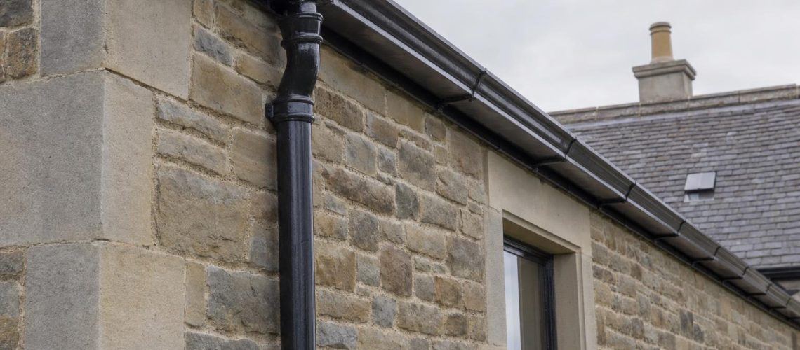
A cast iron gutter should be laid with a slight, continuous fall towards its outlets — typically 1:600 (about 1.7mm per metre), and no steeper than about 1:350 (about 3mm per metre). Capacity is governed far more by the number and position of outlets than by fall: a central outlet draining two ways carries roughly twice the flow of an end outlet, while long runs and corners close to outlets reduce capacity. Because cast iron outlets are fixed fittings and downpipe offsets come in fixed projections, outlet positions must be set out against the drains and the wall line before the order is placed. A G46 moulded gutter can be fixed on fascia brackets, screwed directly through its back above the waterline, carried on rafter brackets, or supported on rise and fall brackets driven into masonry at no more than 915mm centres.
Questions about gutter fall, outlet positions and fixing come to us more often than almost any other technical subject — usually from a contractor or stonemason who is about to set the work out and wants to get it right first time. A cast iron gutter should be laid to a slight, even fall of around 1:600 towards its outlets, with outlets positioned over the drains and close to corners, and with every bracket set to a single string line from the high point to the low point. Get those three things right and almost everything else follows.
This guide is written for the people who design, approve and build cast iron rainwater systems: architects, building surveyors, conservation officers, main contractors, roofers and stonemasons. It applies equally to listed and period buildings and to new work, including extensions built against historic fabric. We use the moulded G46 gutter as our worked example because its flat back and deep section raise particular fixing questions, but the principles apply to every cast iron gutter profile.
Mistakes in setting-out are common because cast iron is less forgiving than lighter materials. Outlets are cast fittings rather than holes cut on site, downpipe offsets come in fixed projections, and the weight of a full gutter demands sound fixings. A decision made casually at ordering stage can leave a downpipe that will not meet its gully, or a gutter that holds water along half its length.
Setting-out matters more with cast iron because the system is made of fixed, cast components that cannot be adjusted on site in the way lighter systems can. The outlet positions, the offset projections and the fall are effectively decided when the order is placed.
Cast iron gutters arrived in quantity in the late eighteenth century as a mass-produced alternative to lead, and the moulded profiles — ogees, the G46 and its relatives — became the standard eaves detail on Georgian, Victorian and Edwardian buildings. Their joints are socket and spigot, sealed and bolted. Their outlets are separate cast fittings, either a short section of gutter with an integral nozzle or a stop end with a nozzle cast into it. Their downpipe offsets are single castings with a set projection.
That has three practical consequences. First, an outlet cannot simply be moved a few hundred millimetres on site; the gutter lengths are cut to suit the fittings, so the fittings must be in the right place from the outset. Second, the distance between the outlet and the wall must match one of the standard offset projections, or be adjusted to do so. Third, the gutter weighs considerably more than a lightweight equivalent, and more again when full of water or snow, so the fixing background and bracket spacing must be designed rather than improvised.
The reward for getting it right is a system that, with periodic painting and clearing, routinely lasts a century or more. Cast iron does not sag or creep, so a fall that is set accurately on day one stays accurate.
A cast iron gutter needs a slight, continuous fall towards its outlet — 1:600 is the usual figure, equivalent to about 1.7mm per metre, and the commonly quoted range runs from 1:600 to a maximum of around 1:350, or about 3mm per metre. Historic building guidance in Northern Ireland recommends a minimum of 1 in 360, which sits at the steeper end of the same range.
The standard method for designing gutters, BS EN 12056-3:2000, does not mandate a particular fall for eaves gutters. Its capacity calculations treat an eaves gutter as level, and a gentle fall of the order of 1–3mm per metre is recommended where it is practicable. In other words, fall is not what makes a gutter big enough; outlets and section size do that. Fall is what makes the gutter drain completely, clear itself of silt and dry out between showers.
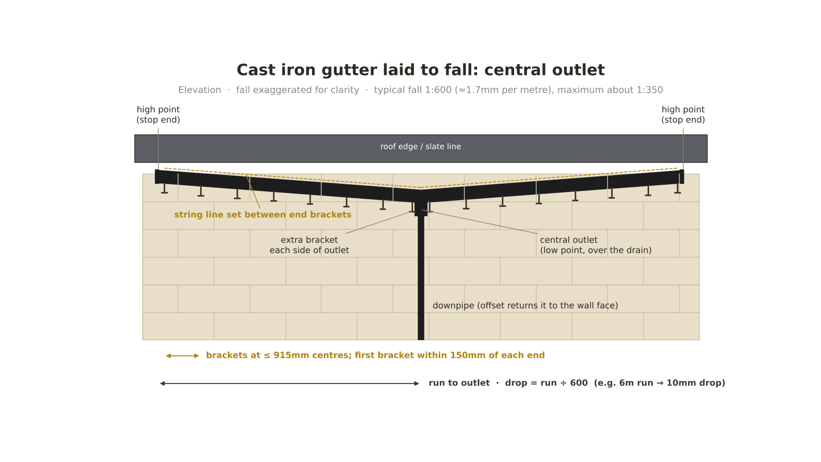
A gutter laid dead level will carry its design flow, but it will not empty. Water stands along the sole of the gutter after every shower, leaves and silt settle into it, and the inside of the casting stays wet for days at a time. On cast iron that is the single most common cause of internal corrosion. A modest fall costs nothing and means the gutter drains dry.
Too much fall is equally unhelpful. On a long run, a steep fall drops the low end of the gutter well below the roof edge, so water can overshoot it in heavy rain, and it makes the gutter visibly out of line with the fascia, the eaves course or the brick and stone coursing below. On a formal elevation — a Georgian front with a strong horizontal cornice line, for example — a gutter that visibly runs downhill can look wrong. This is one reason we favour more outlets and a gentle fall over fewer outlets and a steep one.
The table below converts the usual range into millimetres over typical run lengths, measured from the high point to the outlet.
| Run length to outlet | Drop at 1:600 | Drop at 1:350 |
|---|---|---|
| 3 metres | 5mm | 9mm |
| 6 metres | 10mm | 17mm |
| 9 metres | 15mm | 26mm |
| 12 metres | 20mm | 34mm |
| 15 metres | 25mm | 43mm |
Whatever fall is chosen, the outer edge of the gutter should sit slightly lower than the inner edge, never the reverse, so that any overflow in an extreme storm spills outwards rather than back against the fascia or into the wall head.
BS EN 12056-3:2000 is the design standard for roof drainage, and in England and Wales Approved Document H, Section H3, is the Building Regulations guidance that references it. Together they set how gutters and downpipes are sized; neither prescribes a single fall for eaves gutters.
BS EN 12056-3 sizes a gutter by comparing the run-off from the effective roof area with the tested capacity of the gutter and its outlet. Approved Document H gives a simplified route for smaller roofs, using a design rainfall intensity of 75mm per hour, a table of effective areas adjusted for roof pitch, and a table of capacities for half-round gutters laid level with an outlet at one end. It notes that a fall, a more capacious section or a round-edged outlet can allow a smaller gutter or pipe to be used.
In Scotland the equivalent guidance is in Section 3 of the Building Standards Technical Handbooks, and in Northern Ireland it is Technical Booklet N. For listed buildings, Historic England, Cadw, Historic Environment Scotland and the Historic Environment Division all make the same essential point: the existing system should be repaired or matched like for like wherever possible, and alterations to rainwater goods on a listed building may need Listed Building Consent. Our listed building questions page covers the consent position in more detail.
For a new extension, the drainage design submitted for Building Control should show the gutter and downpipe sizes, outlet positions and the roof areas they serve. Where a moulded profile such as the G46 is specified, ask us for capacity information for the size and outlet arrangement proposed, rather than assuming half-round figures apply.
Gutter outlets should be positioned directly over, or within reach of, the below-ground drains, as close as practicable to corners, and so that no length of gutter has to carry water further than it can handle. Outlet position affects capacity more than fall does.
An outlet at one end of a run means every drop of water travels the full length of the gutter. A central outlet, with the gutter falling towards it from both ends, halves the distance and roughly doubles the flow the same gutter can carry. It also halves the visible drop at each end. Where the drainage layout allows, a central outlet is usually the better design.
Guidance based on BS EN 12056-3 reduces the capacity of an eaves gutter once its length to an outlet exceeds 50 times its overall depth. The length is measured from the stop end to the outlet, or as half the distance between two outlets. The reduction factors are set out below.
| Length to outlet ÷ gutter depth | Capacity reduction factor |
|---|---|
| 50 or less | 1.00 (no reduction) |
| 100 | 0.93 |
| 150 | 0.86 |
| 200 | 0.80 |
For a 100 x 75mm G46 the 50-times threshold is reached at around 3.75m to an outlet; for the 125 x 100mm G46 it is around 5m. Runs can be longer than this, but each extra metre costs capacity, so a long elevation is usually better served by an additional outlet than by a larger gutter.
An angle in a gutter disrupts the flow. Where a corner is less than 2m from an outlet, guidance applies a reduction factor of 0.8 to the gutter’s capacity; between 2m and 4m, the factor is 0.9. On a building with returns and bays, outlets placed sensibly in relation to the angles avoid having to upsize the whole system.
The G46 is produced in 100 x 75mm and 125 x 100mm sizes. Standard outlets are for 65mm and 75mm downpipes, and 100mm round and 100 x 75mm outlets are also available. Larger outlets and downpipes carry more water but should be considered against the building’s proportions; on a modest period house an oversized downpipe can look as wrong as an undersized one performs.
Where a gutter discharges into a rainwater head rather than straight into a downpipe, the head provides a buffer that helps with capacity and can absorb a small misalignment between the outlet and the pipe. The head must be sized to suit the downpipe; we will not recommend a head whose outlet socket leaves too little metal around it to support the pipe.
Because the gutter sits in front of the wall and the downpipe is fixed to it, most outlets need an offset to carry the water back to the wall face. In cast iron, offsets are single castings with fixed projections, so the outlet position must be chosen to match a standard offset size.
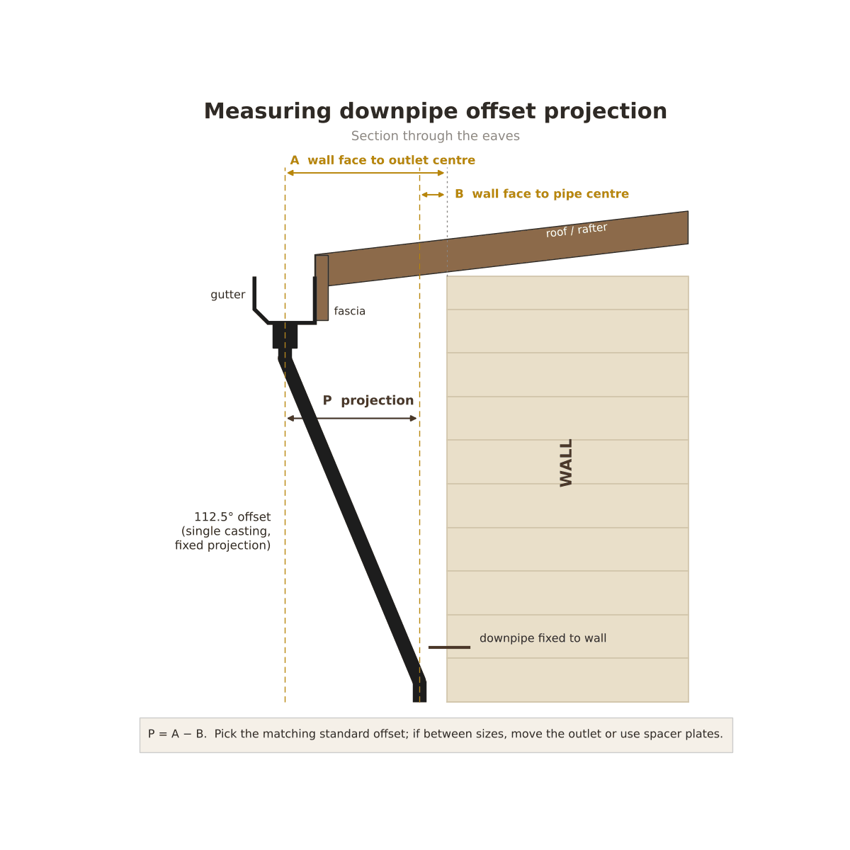
The projection is the horizontal distance from the centre of the gutter outlet to the centre of the downpipe where it sits against the wall. In practice we measure from the wall face to the centre of the outlet, then subtract the distance from the wall face to the centre of the pipe. Our guide to measuring a downpipe offset explains the method with diagrams.
| Downpipe | Standard eaves offsets (112.5°) | Plinth offsets (135°) |
|---|---|---|
| Round 65, 75 and 100mm | 75, 115, 150, 230, 305, 380, 457, 533 and 610mm | Not produced |
| Square 75 x 75 and 100 x 100mm | 56 to 610mm | 75, 115 and 150mm |
| Rectangular 100 x 75 to 150 x 100mm | 56 to 610mm, front and side | 75, 115 and 150mm |
Where the measured projection falls between two standard sizes, there are three options: move the gutter line slightly in or out where the eaves detail allows, adjust the outlet position along the run so that it sits over a point where the projection works, or pack the downpipe off the wall with 30mm spacer plates. Round offsets can also be rotated slightly in plan to take up a small lateral difference; square and rectangular offsets cannot, so they need the correct front or side version.
The outlet must also line up with the drain in plan. If the gully is not directly below the outlet once the offset has returned the pipe to the wall, either the gully moves or a second offset is needed lower down. At ground level, a projecting plinth or string course may require a plinth offset, typically at 135°. All of this is far cheaper to resolve on a drawing than on a scaffold.
A G46 moulded gutter can be fixed in four ways: on fascia brackets, by screwing directly through its flat back into a fascia, on rafter brackets, or on rise and fall brackets driven into masonry. The right choice depends on the eaves construction, not on preference.
The G46 is a deep, flat-backed moulded ogee designed to sit flush against a fascia, which gives it a crisp, architectural line and makes it a long-standing choice for both heritage and new work. Its history and relationship to the other ogee profiles are covered in our history of the ogee gutter.
| Fixing method | Where it is used | Key points |
|---|---|---|
| Fascia bracket | Sound timber fascia | First bracket within 150mm of each end, then at no more than 900–915mm centres, plus an extra bracket at every outlet and angle. Two screws per bracket. |
| Direct fix through the back | Sound timber fascia, flush detail | Screw through the back of the gutter into the fascia without separate brackets. Fixings must stay above the waterline so they do not compromise the gutter’s leak-free capacity. |
| Rafter bracket | No fascia, exposed rafter feet | Top-fixing and side-fixing rafter brackets; centres are governed by the rafter spacing. Provide noggings to support outlets and angles that fall between rafters. |
| Rise and fall drive-in bracket | Masonry or stone eaves with no fascia | Spike driven into the wall, with a threaded stem to set height and fall. At no more than 915mm centres. The G46 bracket has a 300mm spike and 160mm threaded stem. |
How many brackets does a run need, and which type suits your eaves? Our guide to cast iron gutter bracket spacing gives worked bracket counts for typical run lengths, set-out drawings and a profile-by-profile bracket table.
Brackets are mild steel, supplied galvanised or zinc plated, and should be painted with the gutter. Screws should be stainless steel or the zinc-plated gutter screws supplied for the purpose, sized to suit the substrate. The fixing background must be sound: a cast iron gutter full of water, ice or snow will expose a decayed fascia very quickly, so fascias and rafter feet should be inspected and repaired before the new gutter goes up.
Whichever method is used, the gutter should be positioned so that its centre line sits beneath the edge of the roof covering, close enough to catch run-off in light rain and far enough out that it is not struck by sliding snow.
On masonry or stone eaves with no fascia, the gutter is usually carried on rise and fall brackets driven into the joints of the wall, so the fall line and bracket positions need to be agreed with the stonemason before or during the stonework, not after it.
The spike of a drive-in bracket needs a sound bed joint to take it. If the coursing is set out without reference to the gutter, brackets may land on the face of a stone rather than in a joint, forcing either drilling into the stone itself or bracket spacings that no longer suit the gutter lengths. On new stonework the simplest approach is to mark the high point, the low point and the bracket positions on the setting-out drawings, so the mason can leave or rake out joints in the right places.
The threaded stem of a rise and fall bracket allows the height of each support to be adjusted, which is how the fall is achieved on a level course. The usual method is to set the two end brackets first, run a tight string line between them at the chosen fall, and then fix every intermediate bracket to that line.
The same thinking applies to the downpipes. Pipe holdfasts, pipe nails and built-in holderbats should land in joints at sensible heights, and the downpipe line should avoid quoins, window and door dressings, string courses and plinths wherever possible. Where it cannot, the offsets and plinth offsets discussed above need to be identified early. On historic masonry set in lime mortar, fixings should be made in the joints rather than the stone, using lime-compatible methods, so that they can be renewed without damaging the masonry.
Cast iron gutter joints are socket and spigot, made with gutter sealant and a nut and bolt, and they should lap in the direction of fall so that water runs over each joint rather than into it.
In practice that means the spigot end of the upstream length sits inside the socket of the next length downstream. Apply sealant to the socket, bring the lengths together, insert the bolt and tighten until the joint is firm — not so tight that the sealant is squeezed out of the joint. Clean off surplus sealant from the inside of the gutter so that it does not form a dam. Cut ends should be de-burred and touched up with paint before fitting.
Union clips, where used, follow the same principle. Every joint, outlet and angle should be supported by a bracket close to it, as noted above, so that the weight of the gutter is never carried by a joint alone.
Where a new extension meets an existing building, the gutter levels at the junction usually decide the fall for the whole new run, so the existing gutter should be surveyed before the new one is designed.
Older gutters were often laid very close to level, and many have settled over the years. If the new gutter is designed to discharge into the old one, it may add water to a system that already struggles. Wherever possible, we recommend that the new run falls away from the historic building to its own outlet and downpipe, with a stop end at the junction. That keeps the two systems independent and protects the older fabric.
If the new gutter is to read as a continuation of the old, the profile, size and height should match. Where the existing profile is an older moulded section that differs subtly from current patterns, our copy casting service can reproduce it from a sample or measured drawing. Where the host building is listed, the extension and any changes to its rainwater goods will normally fall within the scope of the Listed Building Consent, and the conservation officer may want to see the gutter profile, finish and downpipe positions on the drawings.
Finish matters on mixed old and new work too. Linseed oil paint gives a breathable, low-sheen finish that sits comfortably beside historic paintwork; factory black and primed finishes are also available.
Setting out a cast iron gutter means fixing the outlet positions and fall on paper, transferring them to the building, and fixing every bracket to a single line. The sequence below is the one we recommend.
Most problems we are asked to solve come from a handful of avoidable errors, almost all of them made before the first bracket goes up.
Standard G46 gutters, fittings and brackets are stock or standard items, so lead times are short; bespoke or copy cast profiles take considerably longer, and on complex sites a chargeable site survey is the surest way to get the setting-out right before anything is ordered.
Stock items are typically despatched within 5 to 7 working days of order, and non-stock standard items within 7 to 10 working days — please confirm current availability when you enquire. Bespoke and copy cast components typically require 12 to 14 weeks from pattern approval, and a linseed oil paint finish adds further time. We state lead times at quotation and will not promise a turnaround we have not confirmed.
Where the drainage layout is uncertain, the eaves detail is unusual, the new work meets a historic building, or access is difficult, we recommend our site survey service. It is a chargeable service, and it exists to protect the project: a surveyed set of outlet positions, projections and fixing details avoids the far greater cost of reworking cast iron on a scaffold. For straightforward work, a marked-up elevation and a few photographs of the eaves and drains are often enough for us to advise.
When writing a specification, we suggest stating the profile and size, the outlet positions and sizes, the fall (for example, ‘laid to a continuous fall of 1:600 towards outlets’), the bracket type and maximum centres, the joint method, and the finish. We are glad to help with specification wording.
The examples below are illustrative of the setting-out problems we are commonly asked about on historic buildings. They are representative cases rather than descriptions of specific Tuscan Foundry projects.
A long front elevation had been drained to a single end outlet, and the original moulded gutter overflowed above the entrance in every heavy storm. Rather than enlarge the gutter and lose the historic profile, a second outlet was introduced at the party wall line with a matching rainwater head. Each run was relaid at 1:600 on refurbished brackets. The overflowing stopped, the cornice line was unchanged, and the scheme required no alteration to the historic profile.
The chapel’s eaves are coursed stone with no fascia, and the gutter had been carried on drive-in brackets set wherever a joint happened to fall. Spacings of over a metre had let the gutter sag between supports, holding water. During repointing the mason was given a setting-out drawing of bracket positions and the fall line, joints were raked out accordingly, and new rise and fall brackets were set to a string line at regular centres.
A new rear extension in matching stone was to meet the original gutter at a re-entrant corner. Survey showed the existing gutter was laid almost level and already near capacity. The new G46 gutter was set to fall away from the historic house to its own outlet and downpipe, with a stop end at the junction, so the older system received no additional water and both could be maintained independently.
Replacement downpipes had been ordered from a measured drawing, but on site the outlets sat further from the wall than the drawing showed and the offsets did not reach. Rather than introduce improvised bends, the outlet positions were remeasured, one outlet was moved along the run to sit over the existing gully, and offsets of the correct standard projection were supplied. Spacer plates took up the final small difference at the wall.
Rhones on this granite farmhouse were carried on rhone hooks built into the wall head, and two hooks had failed, leaving a back-fall towards the gable. New hooks were set into the joints during wall head repairs, the fall was re-established at the steeper end of the usual range to clear heavy leaf fall from nearby trees, and the joints were remade lapping towards the outlet.
A cast iron gutter should be laid to a slight, continuous fall of around 1:600, which is about 1.7mm per metre or 17mm over 10 metres. The commonly accepted range runs from 1:600 to a maximum of about 1:350, or 3mm per metre.
They can carry their design flow when laid level, because the standard capacity calculations assume a level gutter, but we do not recommend it. A level gutter never drains dry, so water and silt stand in it and the casting corrodes from the inside. A gentle fall of around 1:600 avoids this.
Use 1:600 as the default. Move towards 1:350 only where the eaves detail allows it and a steeper fall is useful, for example where heavy leaf fall needs clearing. On long runs, adding an outlet is usually better than increasing the fall.
On a long run, a central outlet with the gutter falling towards it from both ends is usually best. It roughly doubles the flow the same gutter can carry compared with an end outlet and halves the visible drop at each end.
Yes. Guidance based on BS EN 12056-3 applies a reduction factor of 0.8 where a corner is less than 2 metres from an outlet, and 0.9 where it is between 2 and 4 metres away.
Capacity starts to reduce once the length to an outlet exceeds 50 times the gutter’s depth. For a 125 x 100mm G46 gutter that is around 5 metres. Longer runs are possible, but each additional metre reduces capacity, so a further outlet is often the better answer.
Measure from the wall face to the centre of the gutter outlet, then subtract the distance from the wall face to the centre of the downpipe. The result is the projection. Choose the standard offset that matches it, and adjust the outlet position or use spacer plates if it falls between sizes.
Round cast iron offsets for 65, 75 and 100mm pipes come in projections of 75, 115, 150, 230, 305, 380, 457, 533 and 610mm. Square and rectangular offsets run from 56mm to 610mm, and square and rectangular plinth offsets are available at 75, 115 and 150mm.
Fix the first bracket within 150mm of each end, then space brackets at no more than 900 to 915mm centres, with an additional bracket at every outlet and angle. Rise and fall brackets driven into masonry should also be at no more than 915mm centres.
Where there is no fascia, use rafter brackets fixed to the rafter feet, or rise and fall drive-in brackets driven into the joints of the masonry. The threaded stem of a rise and fall bracket lets each support be set to the correct height to achieve the fall.
Yes. The G46 has a flat back and can be screwed directly through it into a sound timber fascia without separate brackets, provided the fixings stay above the waterline so they do not create a leak path.
Joints should lap in the direction of fall, with the spigot end of the upstream length sitting inside the socket of the next length downstream. Water then runs over each joint rather than into it.
Where possible, no. We recommend that the new run falls away from the historic building to its own outlet and downpipe, with a stop end at the junction, so the older system is not overloaded and each can be maintained independently.
Often, yes. Altering the profile, outlet positions or downpipe arrangement on a listed building can affect its character and may need Listed Building Consent. Like-for-like repair usually does not, but check with the local conservation officer before work starts.
Stock items are typically despatched within 5 to 7 working days and non-stock standard items within 7 to 10 working days, subject to current availability. Bespoke and copy cast components typically take 12 to 14 weeks from pattern approval.
We recommend a site survey where the drainage layout is uncertain, the eaves detail is unusual, new work meets a historic building or access is difficult. It is a chargeable service that fixes outlet positions, projections and fixing details before anything is ordered.
The essentials are simple. Lay cast iron gutters to a slight, even fall of around 1:600, never dead level and rarely steeper than 1:350. Put outlets where the drains are, near corners, and often enough that no run is overloaded — and prefer central outlets on long elevations. Check every outlet against a standard offset projection before ordering. Fix every bracket to a single string line, at no more than 915mm centres, with extra support at fittings, and agree bracket positions with the stonemason wherever the gutter is carried on masonry.
We supply the full G46 moulded gutter range in both sizes, with outlets, angles, stop ends, union clips, fascia, rafter and rise and fall brackets, and the complete range of cast iron gutters and downpipes, in primer, factory black or linseed oil paint. If you would like us to check a layout, confirm capacities for a moulded profile, or help with specification wording, please contact our team or call 0333 987 4452. Where the setting-out is complex, our site survey service will fix the details before anything is cast.