
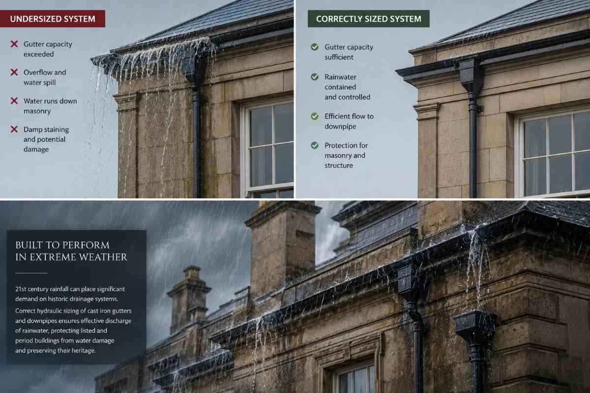
Correctly sizing a cast iron rainwater system for a historic or listed building is one of the most consequential decisions a conservation professional makes. An undersized or incorrectly specified gutter will overtop during heavy rainfall, driving water into the building fabric and triggering the progressive deterioration that causes lasting damage to irreplaceable historic masonry, lime renders, and structural timbers. Yet this is precisely what is happening across the UK’s listed building stock as climate change intensifies storm events well beyond the baseline assumptions on which many existing systems were originally sized.
We have supplied cast iron gutters and rainwater systems to conservation projects since 1893 and we see the consequences of inadequate sizing regularly. Historic buildings designed with generous projecting eaves, high-pitched roofs, and large plan areas generate substantial runoff loads — loads that demand careful hydraulic calculation, appropriate profile selection, and a clear understanding of regional rainfall data. This article explains the principles behind BS EN 12056-3:2000, sets out the key calculations, and explains how to select the right cast iron profile for your project.
The approved standard for rainwater drainage design in the United Kingdom is BS EN 12056-3:2000, which replaced the earlier BS 6367 and provides the methodology for calculating gutter and downpipe sizes for gravity drainage systems. This is the framework that governs all compliant rainwater system design, whether for new build or conservation work.
For heritage buildings, the standard requires designers to classify a project against one of four safety categories based on the consequences of gutter overtopping. Standard residential applications typically fall into Category 2, but most listed buildings — and certainly Grade I and Grade II* properties, churches, and civic buildings — should be designed to Category 3 or above. Category 3 applies a safety factor based on the building’s design life that typically equates to a 225-year return period design storm. For buildings of the highest cultural significance, Category 4 mandates design to the absolute maximum regional rainfall event.
The case for applying the higher category is straightforward: the cost of oversizing a gutter is marginal compared to the cost of repairing damp-affected historic masonry or structurally compromised roof timbers. We always recommend discussing the appropriate design category with the project engineer or conservation specialist at the earliest stage.
The first and most commonly misunderstood step in the calculation is determining the Effective Roof Area (ERA) rather than the simple plan area of the roof. Because UK storms are rarely vertical, BS EN 12056-3:2000 assumes a design wind angle of approximately 27 degrees — meaning rainfall strikes exposed surfaces at an angle. This has a direct consequence for any steeply pitched roof: 50 per cent of the vertical wall area, and 50 per cent of any roof face with a pitch exceeding 70 degrees, must be added to the plan roof area to arrive at the correct ERA.
In practical terms, the effective catchment area is calculated as: ERA = (W/2 + H/2) x L, where W is the horizontal span of the roof from eaves to ridge, H is the vertical height from eaves to ridge, and L is the length of the roof run. For a typical steep-pitched country house wing with a 6m span, a 5m rise, and a 12m run, this yields an ERA of 66m2. Getting this calculation wrong means under-sizing from the outset.
Pitch factors are also applied when working from plan area: a 30-degree pitch carries a factor of 1.29, while a 45-degree pitch carries 1.50, and steeper pitches approach 2.0 at the extremes. Heritage buildings with steeply pitched roofs — and many Georgian, Victorian, and Arts and Crafts properties fall into this category — require careful attention to these multipliers.
Once the ERA is established, the required flow rate (Q) is calculated by multiplying the ERA by the design rainfall intensity (I) for the region: Q = ERA x I. Rainfall intensity is expressed in litres per second per square metre (l/s/m2) and represents the predicted runoff from a two-minute design storm.
Regional design intensities vary across the UK. South-East England uses 0.022 l/s/m2; Wales and the North West use values in the range of 0.015-0.017 l/s/m2; Scotland uses a lower baseline of 0.010 l/s/m2. These figures reflect the intensity of short-duration convective storms rather than total annual rainfall — a distinction that matters enormously for gutter sizing, since it is peak flow that causes overtopping, not average precipitation.
Climate change projections make a compelling case for applying uplifts to these baseline figures. Current evidence indicates that UK summers are on average 15 per cent wetter than the 1961-1990 baseline, and extreme rainfall days are projected to triple by mid-century under a 2-degree warming scenario. For listed building projects with a long design life, engineers should apply a minimum 20 per cent climate change uplift to design rainfall intensity, rising to 35 per cent or more for Category 3 and Category 4 installations.
With the required flow rate calculated, the designer selects a cast iron gutter profile whose certified hydraulic capacity meets or exceeds that figure. Profile selection is not simply a hydraulic decision — on a listed building it must also respect the architectural character of the existing installation. This is where the range of profiles available in authentic sand-cast iron becomes critical.
Standard half-round gutters provide a flow capacity of approximately 1.25 l/s from an end outlet for a 100-112mm profile, draining up to 59.5m2. For larger catchment areas, however, half-round profiles are regularly overwhelmed during intense summer storms because their shallow curved profile cannot contain the depth of fast-moving water generated by heavy rainfall.
Deepflow cast iron profiles address this directly. By increasing the depth of the gutter wall without significantly increasing the width, deepflow profiles can nearly double the end-outlet capacity to approximately 2.1 l/s, draining up to 100m2 of roof. They are particularly well suited to steeply pitched heritage roofs and longer runs without intermediate outlets.
Moulded ogee (Victorian ogee) profiles provide a flow capacity of around 2.2 l/s from an end outlet, draining up to 104m2, while also delivering the decorative, sharp-featured facade associated with Victorian civic and residential buildings. Box gutter profiles offer the highest volume-to-width ratio and are appropriate for large institutional roofs, parapet installations, and industrial heritage buildings — a 150mm x 100mm box profile can drain up to 280m2 from a centre outlet.
A common specification error on heritage buildings is selecting a high-capacity gutter profile while retaining an undersized downpipe. The downpipe — and specifically the transition at the gutter outlet — is typically the bottleneck of the entire system. We strongly recommend the installation of cast iron hopper heads at the gutter-to-downpipe junction on all heritage projects. Hopper heads serve as hydraulic buffers, absorbing peak flow surges and providing a smooth, rounded entry into the vertical pipe stack.
Gravity rainwater downpipes are designed to operate at partial fill — they must not run completely full, as this triggers siphonic action. A 75mm round cast iron downpipe should not carry more than 4-5 l/s in gravity flow conditions; a 100mm round pipe can safely carry over 10 l/s. For large heritage roofs — churches, country houses, civic buildings — rectangular or square downpipes frequently provide the most appropriate combination of hydraulic capacity and period character.
Outlet positioning is also a significant design variable. Placing a downpipe at the centre of a gutter run rather than at one end halves the effective drainage length on each side, doubling the roof area that can be drained without changing the gutter profile.
For long gutter runs, BS EN 12056-3:2000 requires the application of a frictional resistance reduction factor (Fl) when the run length exceeds 50 times the nominal gutter depth. For a standard 100mm deep gutter spanning 10 metres to a single end outlet, the length-to-depth ratio is 100, yielding a reduction factor of approximately 0.833 — meaning the gutter’s certified flow capacity must be reduced to 83.3 per cent of its standard rating.
Corners introduce further flow resistance. BS EN 12056-3:2000 requires a standard 15 per cent reduction in overall gutter capacity for any run incorporating a corner. Corners within 2 metres of a downpipe outlet carry an additional capacity factor of 0.80; corners between 2 and 4 metres from the outlet carry a factor of 0.90. On complex historic buildings with internal angles, returns, and bays, these reductions accumulate quickly.
At Tuscan Foundry, we have been supplying authentic sand-cast iron rainwater systems to historic and listed buildings since 1893. We understand that specifying the correct gutter profile is not simply a matter of selecting from a catalogue — it requires an understanding of hydraulic calculation, profile geometry, and the specific demands of the building in question. Where projects involve complex rooflines, failing timber troughing, or significant hydraulic challenges, we offer a chargeable on-site survey service that provides the detailed assessment needed to specify with confidence. Standard stock items are available for prompt despatch; bespoke and copy-cast components carry a lead time of 8-10 weeks. To discuss your project, please contact us on 0333 987 4452 or visit tuscanfoundry.com.